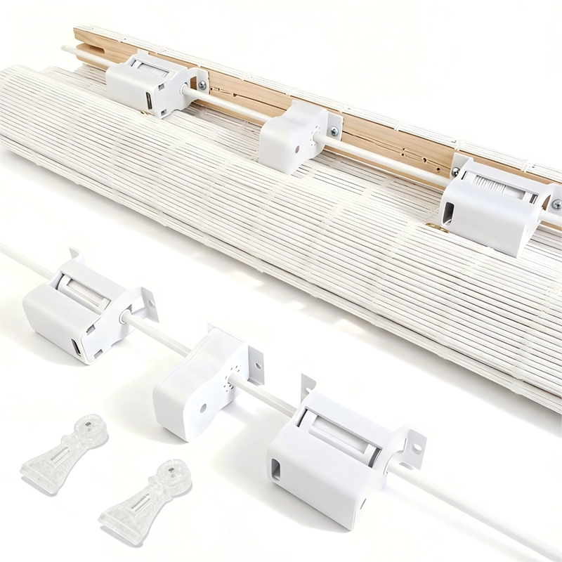
How the Spring System Works in Real Operation for Cordless Blinds
Revealing the “Invisible Power” Behind Seamless Motion
Quick Summary
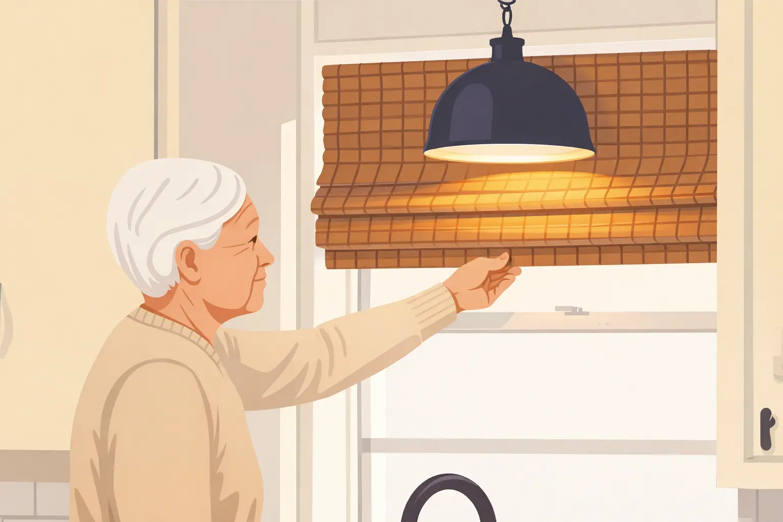
Cordless blinds feel effortless because a spring system continuously balances changing gravity torque across the full travel.
The difference between “smooth today” and “stable for years” is dynamic compensation—force matching plus controlled braking, validated by life-cycle testing.
1. Introduction: The Magic Is in the Motion
A gentle push. The blind moves. Release—and it stops where you expect.
What looks simple is actually a continuous negotiation between gravity torque, spring torque, friction, and braking authority.
From a product manager’s view, the real market question is practical:
why do some cordless blinds begin to drift after 6 months, while others remain stable for 10+ years?
The difference is rarely “one better part.” It’s whether the system can maintain Dynamic Compensation in real use.
| System Type | Common Behavior | When Complaints Appear |
|---|---|---|
| Spring-only (no matched brake) | Mid-travel drift / inconsistent stop | 3–6 months |
| Friction-heavy compensation | Feels “tight” early, ages unpredictably | 6–9 months |
| Integrated torque-governed system | Predictable hold across travel | 5+ years (low complaint rate) |
2. Core Principle: Torque vs. Gravity (The Battle of Physics)
Cordless blinds do not fight “weight” directly. They fight torque demand, which changes as fabric rolls in and out.
The key relationship is simple:
T = F × r
Where F is the gravity load (in newtons) and r is the effective roll radius.
As the blind lowers, roll diameter decreases—so required holding torque decreases too.
This is why a “good feel” at one position does not guarantee stability everywhere.
| Item | Value | Unit / Notes |
|---|---|---|
| Fabric Density | 1.2 | kg/m² |
| Fabric Weight | ≈ 23.5 | N (1.2 × 1 × 2 × 9.8) |
| Bottom Bar Mass | 0.8 | kg |
| Bottom Bar Weight | ≈ 7.8 | N (0.8 × 9.8) |
| Total Base Load | ≈ 31.3 | N |
| Target Spring Force (with margin) | ≈ 34.4 | N (≈ +10% for friction & system losses) |
| Position | Effective Radius | Required Torque | What Can Go Wrong |
|---|---|---|---|
| Top (fully rolled) | 28 mm | ≈ 0.96 N·m | Impact/noise if release is not governed |
| Mid-travel | 22 mm | ≈ 0.75 N·m | Creep appears if force band is not matched |
| Bottom (fully extended) | 18 mm | ≈ 0.62 N·m | Sluggish lift if spring output attenuates |
3. Three Stages of Real Operation
Stage A: Initiating the Lift (Static Friction)
The first few millimeters of movement are mechanically the hardest.
Systems must overcome static friction, which is typically higher than dynamic friction.
If startup torque margin is too small, users feel hesitation and “stick-slip” behavior.
| Friction Mode | Relative Resistance | Design Implication |
|---|---|---|
| Static Friction | ≈ 1.2× | Needs extra startup torque margin |
| Dynamic Friction | ≈ 1.0× | Controls smooth travel once moving |
Stage B: Mid-Travel Stability (Where Real Use Happens)
Mid-travel is the most frequently used zone, so instability shows up here first.
A poorly matched spring curve can cause slow downward drift or unexpected upward creep.
Most “it was fine at installation” failures appear when the system finally reaches its full operating envelope
after early run-in (typically within 500–1,000 cycles).
 |
 |
| Metric | Target | Why It Matters |
|---|---|---|
| Torque Fluctuation | ≤ ±5% | Prevents creep and “position memory loss” |
| Pull Force | ≤ 30 N | Keeps operation comfortable for end users |
| Rise Speed | 0.1–0.2 m/s | Avoids slam-up and sluggish recovery |
| Noise Level | ≤ 35 dB | Supports “Silent Operation” positioning |
Stage C: End-Stop Braking (Energy Must Be Governed)
At full extension and full retraction, stored energy peaks.
Without a matched brake, the blind can hit the end stop, generating noise and shock loading.
The brake’s role is not to “fight the spring” but to shape the release and lock position reliably.
| Scenario | Typical Outcome | Business Impact |
|---|---|---|
| No matched braking | Impact, noise spikes, faster wear | Higher warranty exposure |
| Matched brake system | Controlled deceleration, stable lock | Lower claims, premium feel |
4. Why an Integrated System Beats Standalone Parts
“Good parts” do not automatically form a good system.
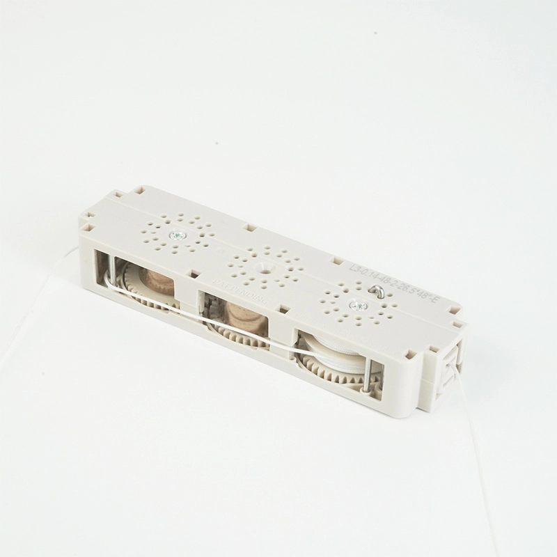
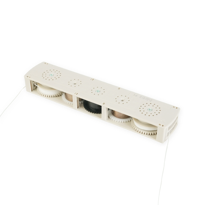
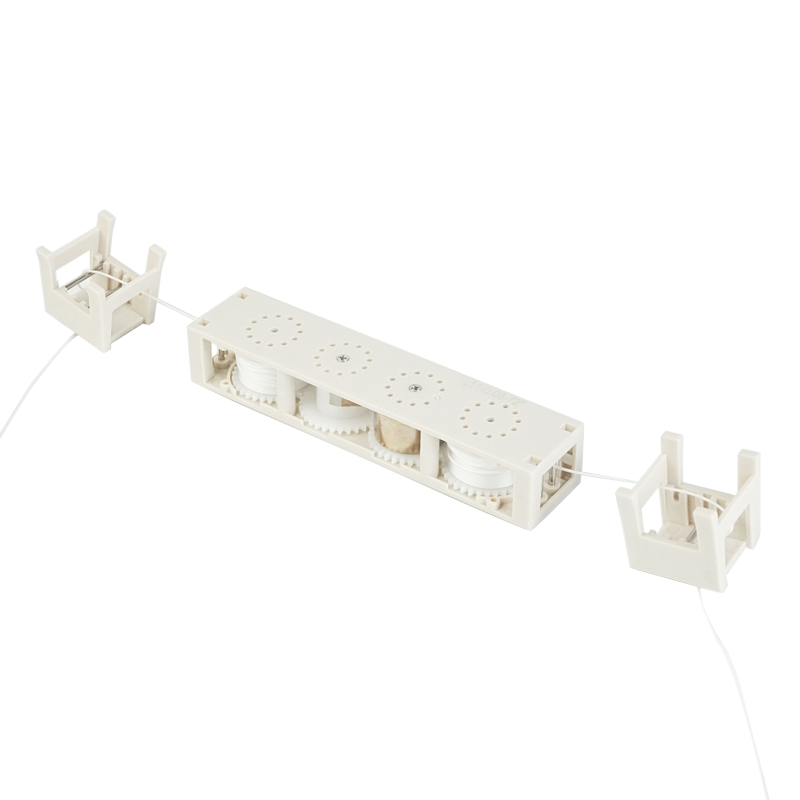
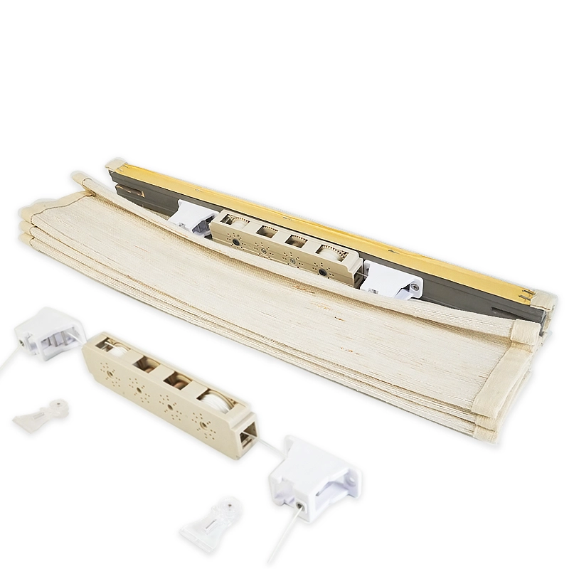
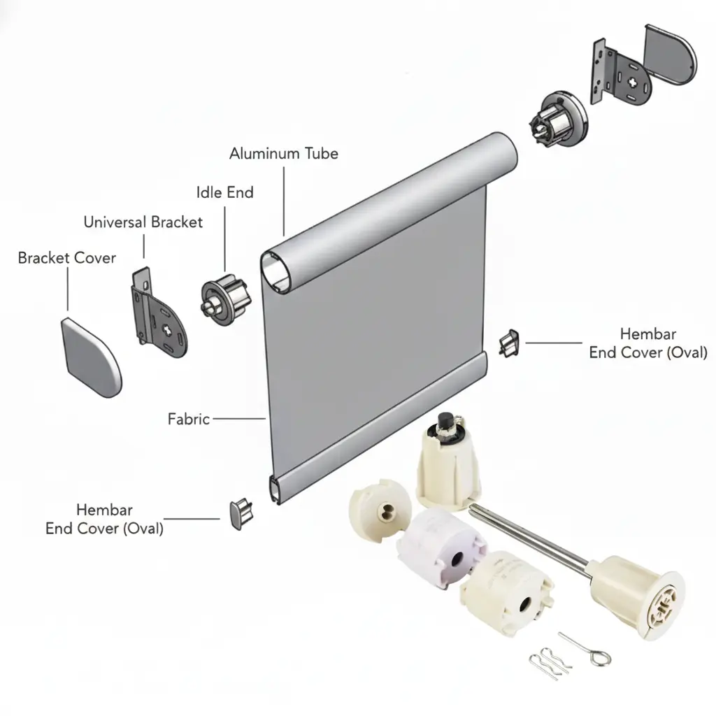
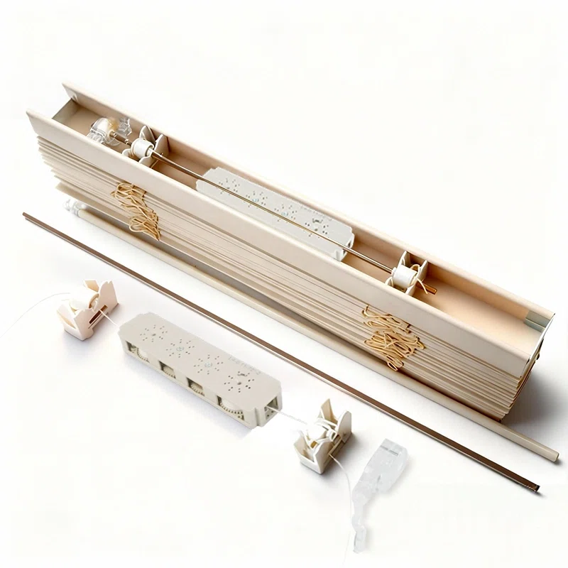
Springs, tubes, brakes, shafts, and bearings must be designed as a matched set.
When tolerances and force bands are not aligned, performance becomes unit-to-unit inconsistent and lifespan drops.
| Concentricity Deviation | Observed Effect | Risk |
|---|---|---|
| ≤ 0.1 mm | Stable travel, low noise | Low |
| ≈ 0.2 mm | Force fluctuation rises (≈ +10%) | Medium |
| ≥ 0.3 mm | Noise spikes, accelerated wear | High |
Fatigue Life and Life-Cycle Validation
Reliability must be proven with testing—not inferred from “it feels smooth today.”
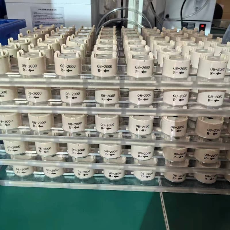
Professional validation includes cycle testing, force decay tracking, and environment checks
to ensure the system maintains predictable behavior over its life cycle.
| Test Item | Benchmark | Pass Criteria |
|---|---|---|
| Cycle Validation | 5,000+ cycles | Force decay ≤ 5% |
| Design Target | 100,000 cycles | Long-term stability |
| Temperature Range | -20°C to 60°C | No functional instability |
| Humidity Stress | 95% RH (typical) | No abnormal noise / drift |
Environmental Adaptation
Temperature and humidity change material behavior and friction conditions.
In product planning, this is why “life-cycle” is a stronger selling point than “smoothness.”
Life-cycle stability reduces the buyer’s warranty cost and protects brand reputation.
5. Conclusion: Your Partner in Cordless Excellence
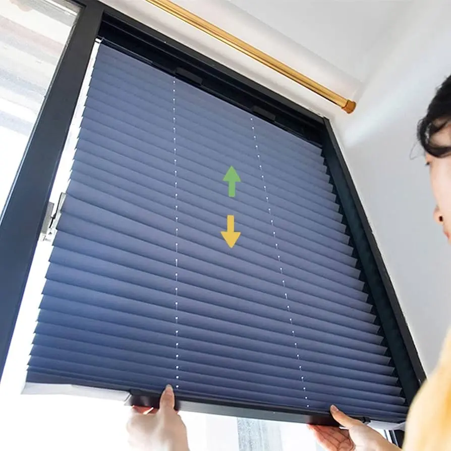
A spring system is not just a part. It is a torque-governed architecture that defines the real-world experience of a cordless blind:
silent operation, stable mid-travel stopping, controlled end-stop behavior,
and life-cycle predictability.
 |
 |
Field Insight
“Smooth” is a moment. Predictable hold is a life-cycle requirement.
If your system depends on friction to feel stable, it may pass early checks but fail after run-in.
Force matching first, braking second, and verification always.
CTA: Want to see our spring system test reports? Request a technical data sheet today.