Braking Is a Material Science Problem, Not a Mold Problem
If your cordless system drifts, chatters, or ages badly,
the root cause is rarely geometry alone.
It’s almost always the material behavior you didn’t model.
Quick Summary
In cordless blind systems, braking performance is often blamed on mold precision or part geometry.
In reality, long-term stability, noise behavior, and early-cycle failures are driven primarily by
material friction behavior, creep resistance, and thermal stability.
Brakes fail not because they are poorly shaped—but because their materials behave unpredictably under load, heat, and time.
Engineering sanity check: if friction (μ) shifts by ±0.10, or compression set increases by ≥1–2%,
a “perfect” mold can still produce a brake that drifts after 200–1,000 cycles and chatters above ~40 dB.
Why “Perfect Molds” Still Produce Unstable Brakes
Mold Precision vs Material Behavior: Failure Source Comparison
| Failure Symptom | Mold / Geometry Cause | Material Behavior Cause |
|---|---|---|
| Early drift (0–1,000 cycles) | Rare | Friction coefficient instability |
| Hold force decay | Minor alignment loss | Polymer creep / compression set |
| Chatter / noise | Rare | Stick-slip (μs / μk mismatch) |
| Temperature sensitivity | Negligible | Thermal softening of polymer |
Molds define shape.
Brakes define behavior.
In the last few weeks, we’ve discussed why:
- Early failures dominate the 0–1,000 cycle window
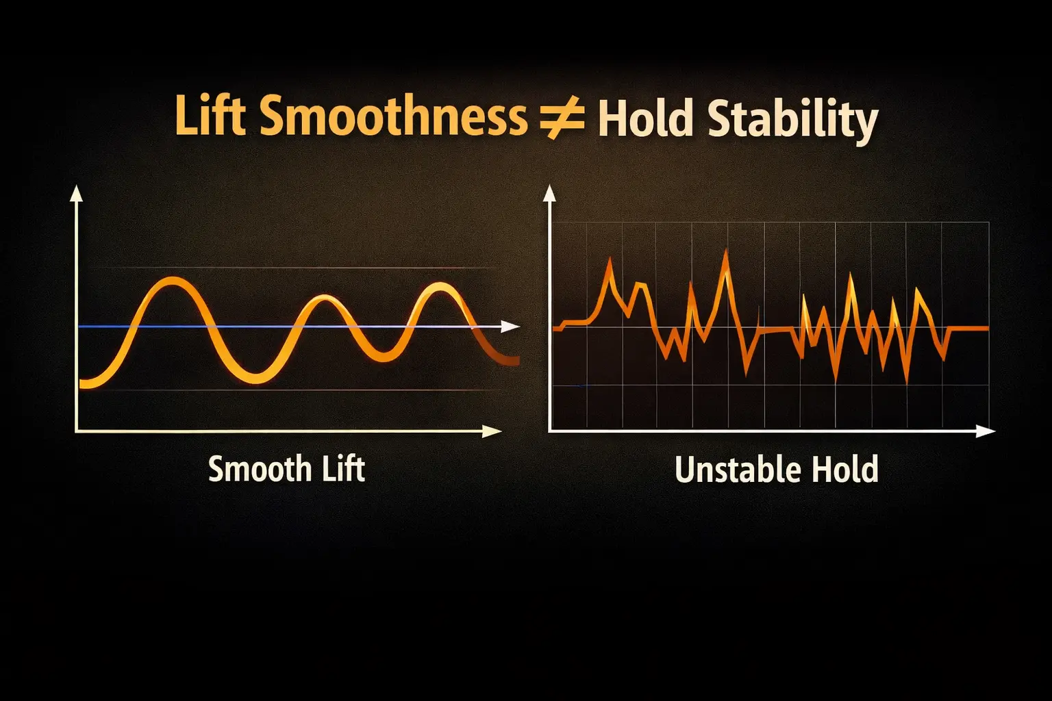
- Lift smoothness does not guarantee hold stability
- Force bands must converge before braking can govern motion
Yet many OEM teams still default to:
“Tighten the mold tolerance.”
That helps alignment.
It does nothing to fix:
- Friction coefficient drift (e.g., μ from 0.35 → 0.22 after run-in)
- Thermal softening under sun-exposed windows (parts seeing 45–60 °C locally)
- Polymer creep under sustained load (thickness loss 0.05–0.20 mm over weeks)
- Stick-slip chatter after run-in (noise spikes typically 35–55 dB)
Those are not mold problems.
They are material science problems.
Hard truth: a tolerance improvement of 0.02 mm cannot compensate for a material whose friction varies
±20–30% with temperature, polishing, or compression history.
What a Brake Actually Does (Engineering Reality Check)
Real Operating Conditions of Cordless Brake Interfaces
| Parameter | Typical Range | Why It Matters |
|---|---|---|
| Interface temperature | 20–60 °C (local) | μ drift and creep accelerate above ~45 °C |
| Contact pressure | 0.3–1.5 MPa | Drives compression set and surface polish |
| Sliding speed | < 5 mm/s | High stick-slip risk at low speed |
| Hold duration | Minutes to hours | Creep dominates long-term behavior |
A cordless brake does not “stop” motion.
It must:
- Continuously dissipate spring energy across full travel (not just at mid-height)
- Maintain predictable friction across temperature (typically a practical range of 20–60 °C)
- Resist deformation under constant contact pressure (often in the 0.3–1.5 MPa band depending on design)
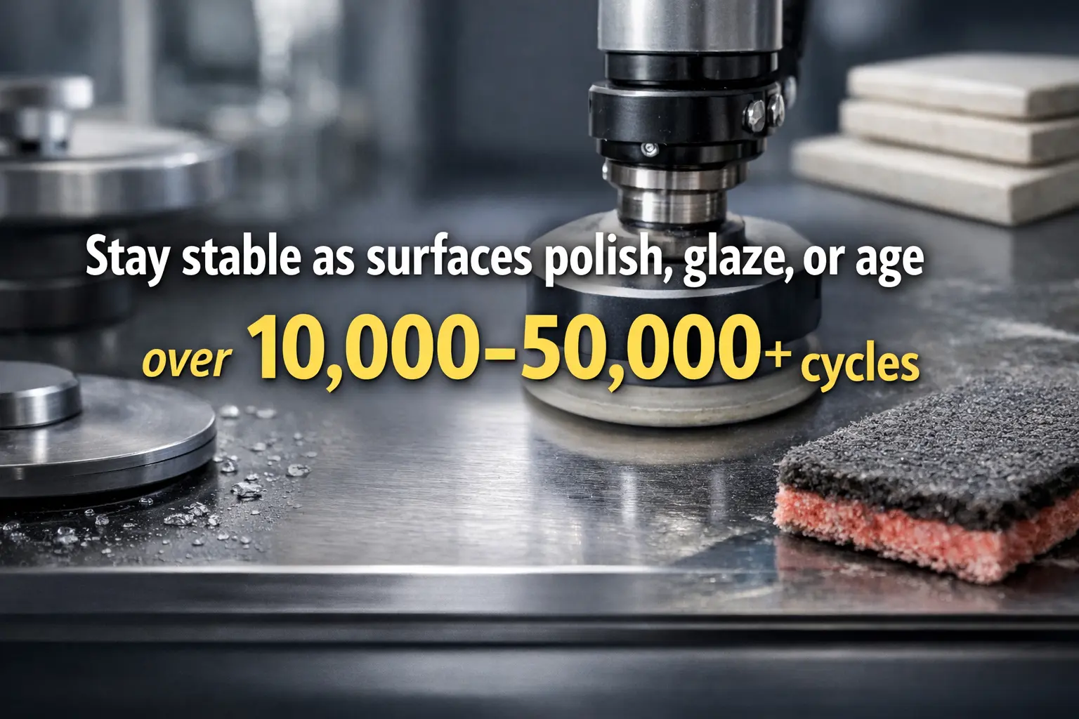
- Stay stable as surfaces polish, glaze, or age over 10,000–50,000+ cycles
This means the brake material is operating in a hostile regime:
- Low speed (micro-motion)
- High contact time (minutes to hours of “hold”)
- Repeated micro-slip (stick-slip risk rises when μ_s/μ_k ratio is high)
- Moderate but persistent heat (temperature-driven μ drift is common)
Geometry sets the stage.
Material behavior writes the script.
Practical benchmark: if your brake can’t keep hold drift under ≤2–3 mm / 10 min at multiple heights
(top / mid / bottom) after 500-cycle run-in, you don’t have “a tuning problem”—you have a behavior problem.
Why Generic Plastics Fail in Cordless Braking
Common Brake Material Failure Modes (Observed Data)
| Material Type | Observed Issue | Typical Data Range |
|---|---|---|
| Unfilled ABS | Thermal μ drop | μ −0.10 to −0.15 @ 50 °C |
| Low-grade Nylon | Moisture & creep | 1–3% compression set |
| Recycled blends | Inconsistent μ | ±20–30% batch variation |
| Single-material pads | Surface glazing | Drift after 300–800 cycles |
Many mass-market systems rely on commodity plastics for braking:
- Unfilled ABS
- Low-grade Nylon
- Recycled polymer blends
They look fine on day one.
They often even feel “smooth” in a short-stroke demo.
Then reality arrives—usually within 200–1,000 cycles and one hot window week.
- Creep: Contact surfaces deform, reducing effective friction (compression set often jumps from <0.5% to 1–3%)
- Thermal drift: Coefficient of friction drops as temperature rises (μ change of 0.05–0.15 is not rare)
- Surface glazing: Micro-polishing creates sudden slip zones (hold performance becomes “random”)
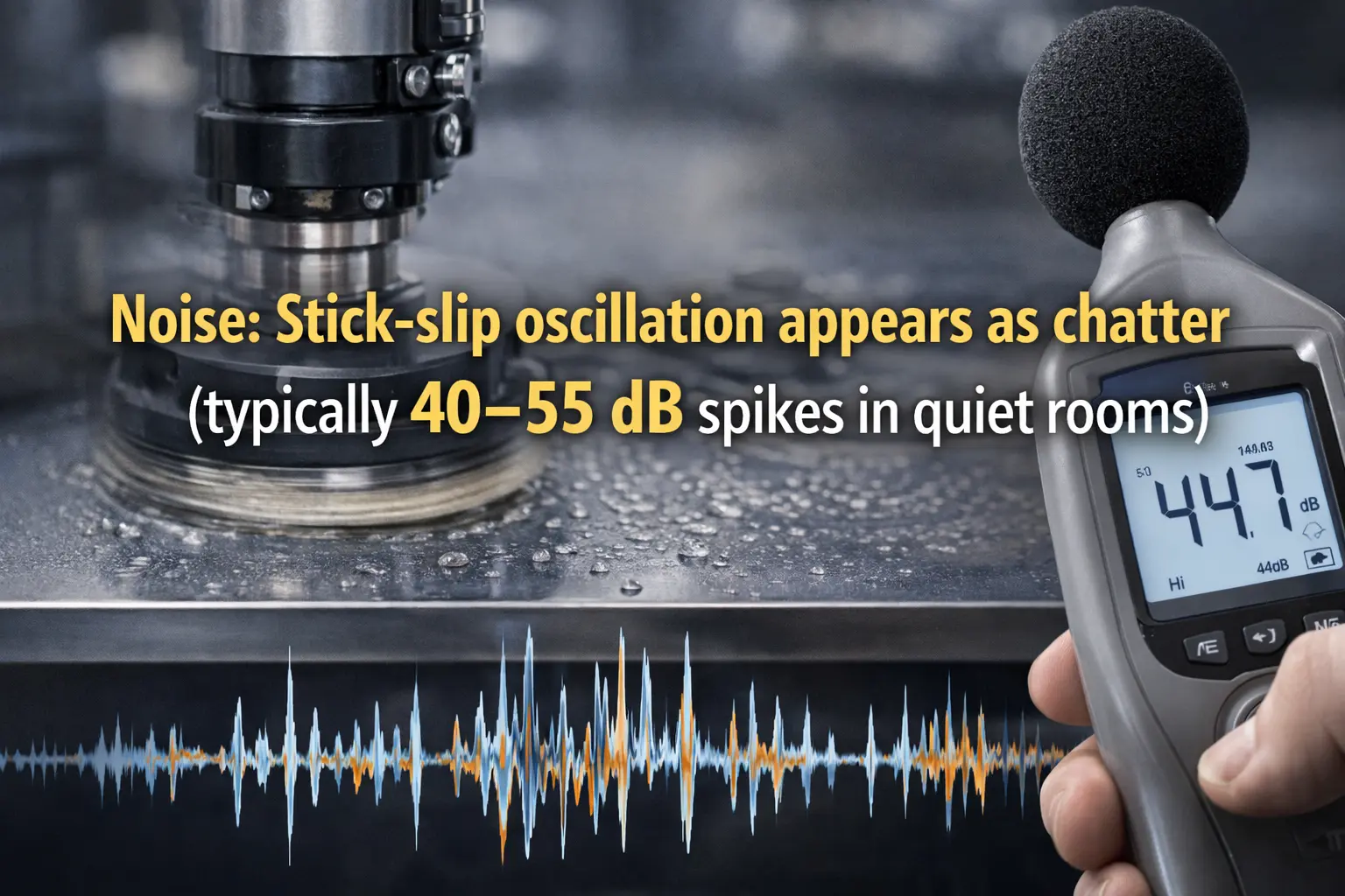
- Noise: Stick-slip oscillation appears as chatter (typically 40–55 dB spikes in quiet rooms)
None of these are visible in CAD.All of them show up after installation—right when your customer stops being polite.
Material-First Braking: What Actually Works
Material-First Braking: Engineering Target Windows
| Metric | Target Value | Why It Matters |
|---|---|---|
| Friction coefficient drift | ≤ ±0.05 | Predictable hold & feel |
| Compression set (72 h) | ≤ 0.05 mm | Long-term holding stability |
| Early-cycle convergence | ≤ 500 cycles | Avoid 0–1,000 cycle failures |
| Noise during slow motion | ≤ 35–40 dB | Eliminate stick-slip chatter |
High-stability cordless systems start with material selection, not tooling.
Key material traits that matter more than mold accuracy:
- Stable friction coefficient across 20–60 °C (target μ drift ≤±0.05)
- Low creep rate under sustained compression (target thickness change ≤0.05 mm over a 72-hour hold)
- Controlled surface wear (no glazing, no powdering; stable transfer film if applicable)
- Predictable run-in behavior during the first 300–500 cycles (no sudden μ cliff)
This is why premium systems move toward:
- Engineering polymers with internal lubricity (lower stick-slip probability)
- Fiber-reinforced or mineral-filled compounds (better creep resistance, thermal stability)
- Hybrid friction stacks instead of single-material pads (separate “feel” layer from “hold” layer)
The mold still matters—but only after the material is right.
Rule of thumb: if your friction stability and creep stability are not quantified,
“mold improvement” becomes an expensive way to feel productive.
Braking Cannot Fix an Unstable Force Band
One last reminder from earlier discussions:The brake does not define stability.
It governs motion inside an already stable force band.
If the spring output is drifting, collapsing, or mismatched:
- More brake friction increases pull force (often pushing user effort above 30–50 N)
- Noise risk goes up (stick-slip becomes more likely)
- User feel gets worse (the “premium” feeling evaporates fast)
Material-first braking only works when:
- Spring torque is controlled (variation bounded, not “hope-based”)
- Force variation is bounded across travel (a practical target is ≤±5–7% for premium feel)
- Early-cycle convergence is verified (run-in + full-travel checkpoints)
 |
|
Otherwise, you are asking materials to hide a system-level imbalance.
They won’t.
Translation: if the force band is unstable, your brake becomes a “stress concentrator” for failure—
it will creep faster, glaze sooner, and chatter louder.
Field Insight
- Braking failures are rarely caused by “bad molds”
- Friction stability (target μ drift ≤±0.05), creep resistance (thickness loss ≤0.05 mm / 72 h), and thermal behavior (20–60 °C) dominate real performance
- Generic plastics behave well in CAD—and poorly after 200–1,000 cycles in real homes
- Material science determines whether braking authority survives aging and heat
- A brake can govern motion, but it cannot rescue an unstable force system
Engineering FAQ (Technical, Quantified)
Q1: What friction coefficient (μ) range is “usable” for cordless braking?
There isn’t a universal μ number because geometry and contact pressure differ, but a practical target is:
μ stability more than μ magnitude.
If μ shifts more than ±0.05 across 20–60 °C or after 500-cycle run-in,
you should expect hold drift and chatter even with perfect tooling.
Q2: How do I quantify “hold drift” in a way that catches material problems early?
Use a time-based hold test at multiple heights (top/mid/bottom):
record drift over 10 minutes, then over 60 minutes.
A practical screening target is ≤2–3 mm / 10 min and ≤5–8 mm / 60 min after run-in.
If results worsen sharply at higher temperature, that’s material thermal behavior—not geometry.
Q3: What run-in length is enough to expose glazing or stick-slip risk?
For many cordless brake interfaces, the first meaningful signal appears by 300–500 cycles.
If chatter appears or holding becomes inconsistent after ~500 cycles, you likely have surface film instability
(polish/glaze) or creep-driven contact pressure decay.
Q4: What compression-set / creep threshold should trigger a material change?
If a brake pad or friction element shows ≥1–2% compression set (or equivalent measurable thickness loss)
after a 72-hour static load soak at elevated temperature, expect long-term drift.
For higher stability platforms, aim for thickness change ≤0.05 mm over the same soak.
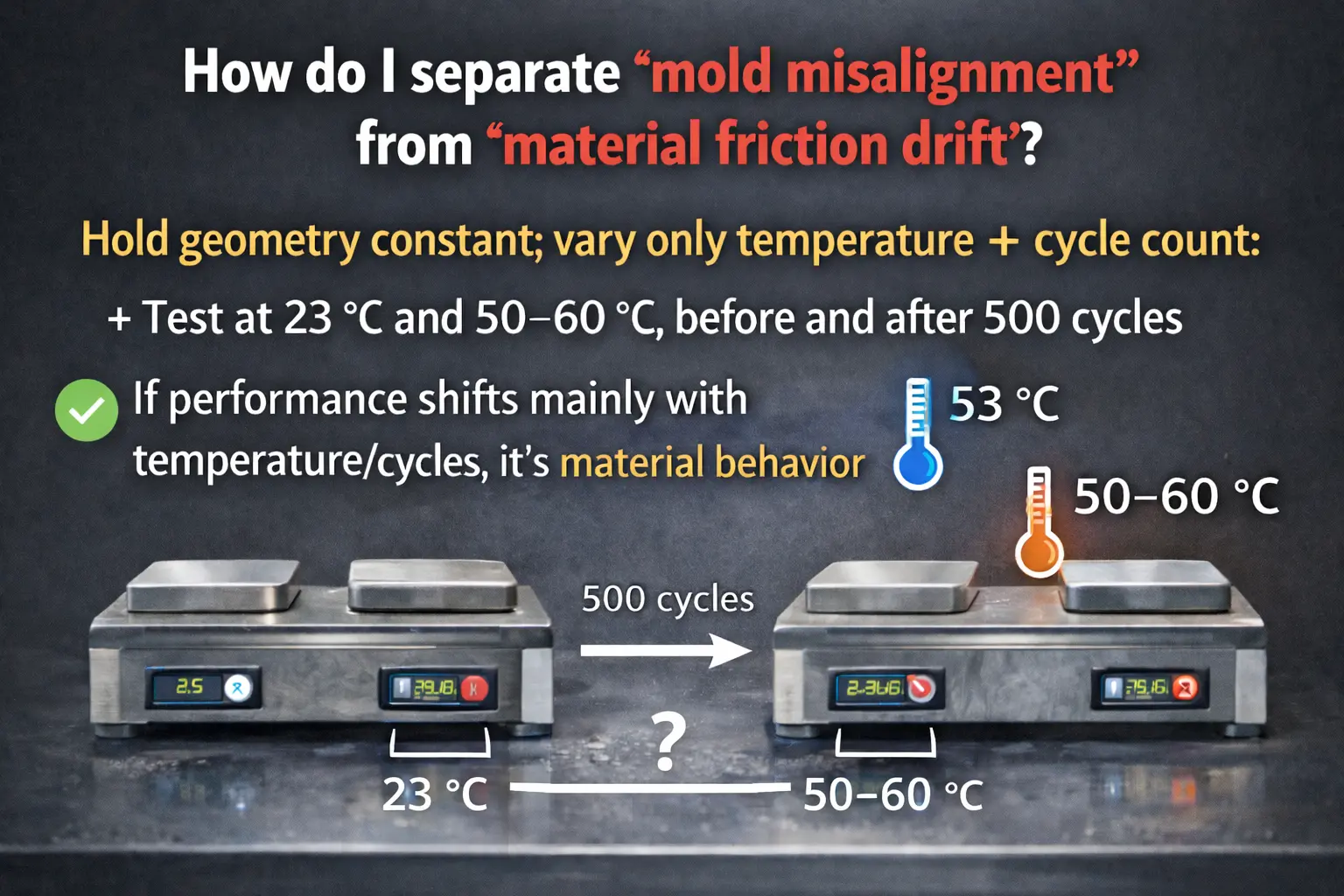
Q5: How do I separate “mold misalignment” from “material friction drift”?
Hold geometry constant and vary only temperature + cycle count:
test at 23 °C and 50–60 °C, before and after 500 cycles.
If performance shifts mainly with temperature/cycles, it’s material behavior.
If performance is inconsistent unit-to-unit at the same conditions, then alignment/tolerance may be dominating.
Q6: What noise level indicates stick-slip rather than normal sliding?
In quiet interior environments, random spikes above ~40 dB during slow motion often correlate with stick-slip.
If the system is smooth at mid-travel but chatters near top/bottom after run-in,
you’re likely seeing a friction regime change as contact pressure and surface condition shift.
Q7: What temperature window should braking materials be validated for?
A practical validation window for sun-exposed consumer use is 20–60 °C at the interface,
even if ambient is lower. If μ or creep behavior changes dramatically above 45 °C,
field failures will cluster in summer or south-facing installations.
Q8: Can adding “more brake friction” fix drift without hurting user feel?
Rarely. Increasing friction often pushes pull effort above the comfort band.
If user pull force climbs beyond 30–50 N, complaints show up fast.
A better approach is stabilizing μ (material selection + surface behavior), then tuning geometry for acceptable effort.
Q9: What test sequence best predicts early-cycle failures (0–1,000 cycles)?
Do a controlled run-in to 200–500 cycles, then measure:
(1) hold drift at top/mid/bottom,
(2) pull force profile across travel,
(3) temperature sensitivity at ~50 °C interface condition.
If results “move” across those checkpoints, your system hasn’t converged—brake tuning will be unstable.
Q10: What’s the simplest “material-first” acceptance criterion for braking stability?
Pick three numbers and be ruthless:
μ drift ≤ ±0.05 (temp + run-in),
hold drift ≤ 2–3 mm / 10 min (multi-height),
creep thickness loss ≤ 0.05 mm / 72 h (static soak).
If a material can’t hit these, your mold will take the blame for a crime it didn’t commit.