Quick Summary
The R38L Spring Lift Mechanism is a professional-grade cordless system for roller shades.
Built around a POM Spring Box with an internal 301 stainless steel constant force spring,
the system delivers controlled lift, reliable braking, and scalable load capacity.
Designed for OEM manufacturers, the R38L supports up to five Spring Boxes on a single Shaft,
making it ideal for wide and heavy roller shade applications.
Spring Lift Mechanism System Overview
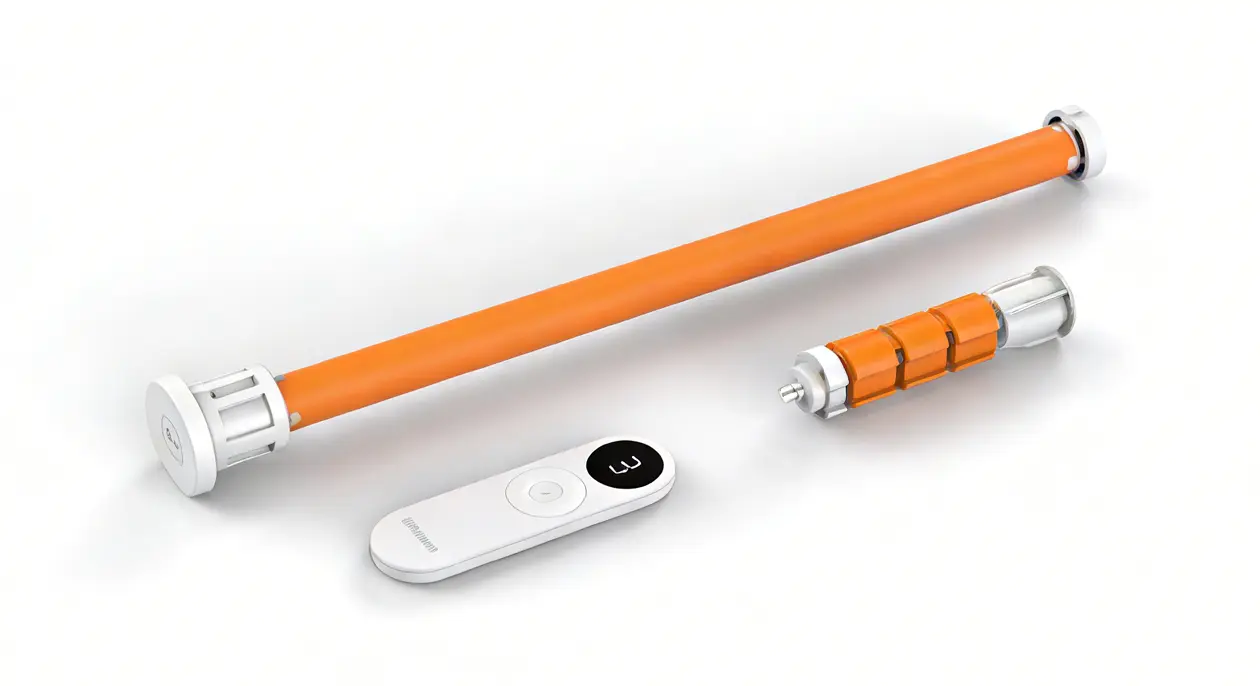
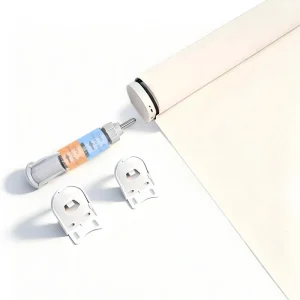
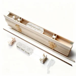
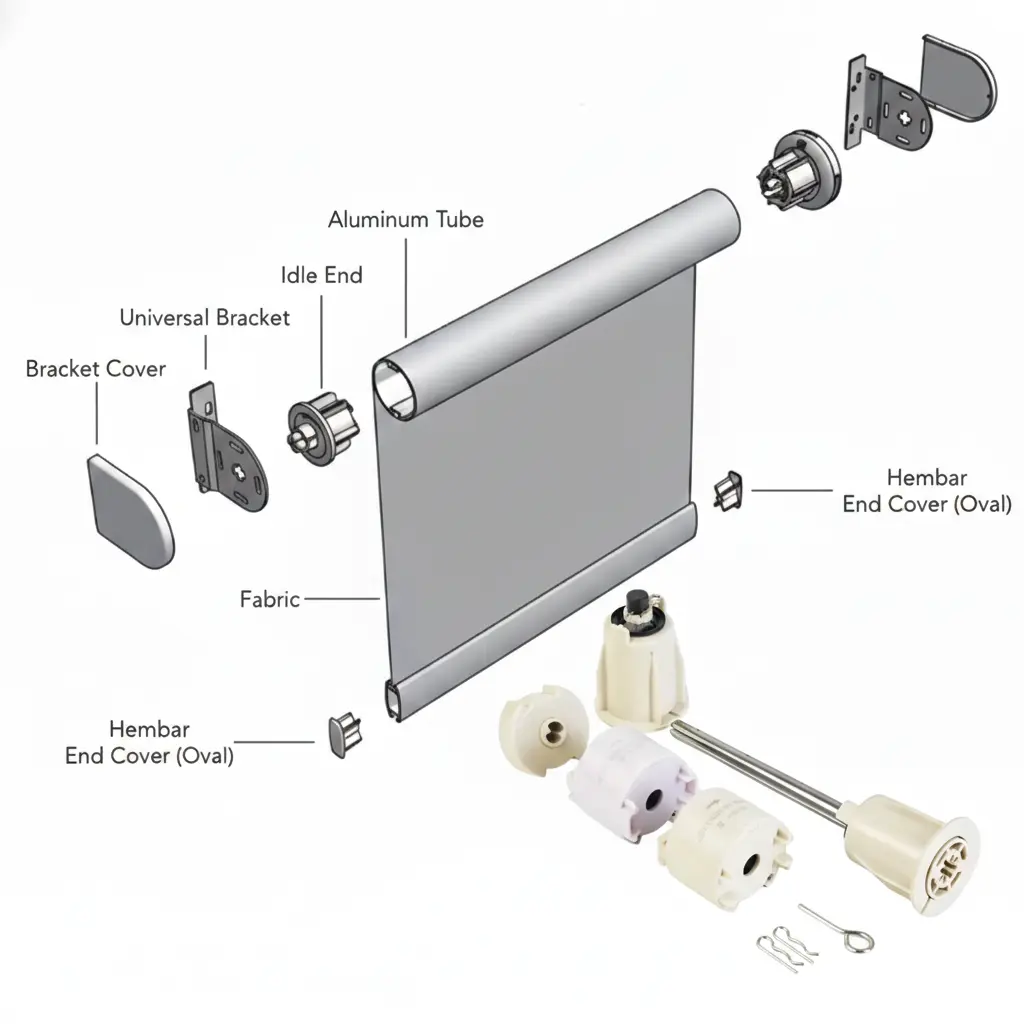
The R38L Spring Lift Mechanism is a mechanical cordless lifting system installed inside aluminum roller tubes.
It replaces traditional cords or chains while improving safety, stability, and user experience.
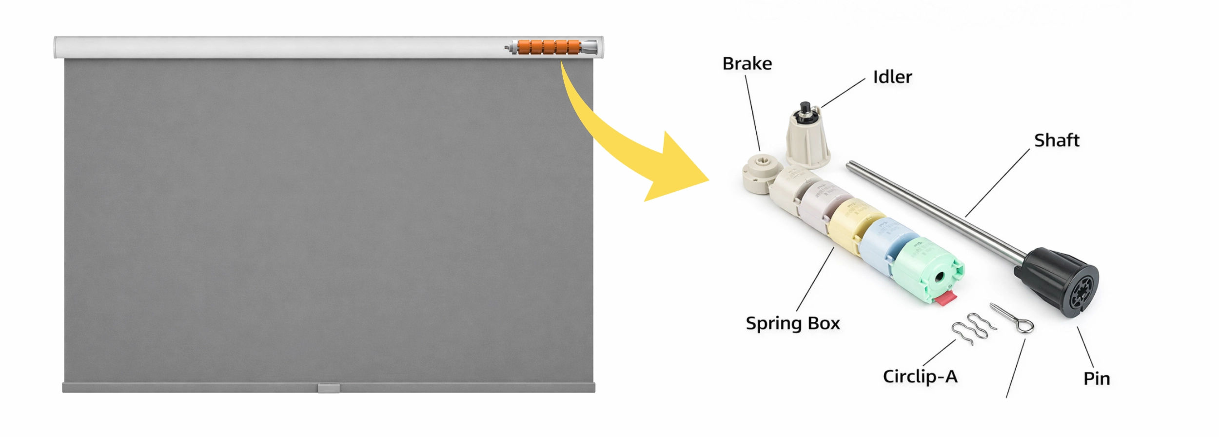
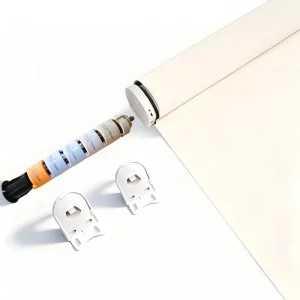
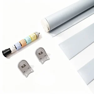
The complete system consists of:
- Spring Box – Core energy storage unit
- Brake – Anti-drop holding component
- Shaft – Structural carrier for multiple Spring Boxes
- Circlip – Fixing component between Spring Box and Brake
- Pin – Locking pin used during pre-winding
Spring Lift Mechanism Installation Overview
Step 1: Spring Box and Shaft Assembly
Install the required number of Spring Boxes onto the Shaft in sequence
and secure each unit using the appropriate Circlip.
Step 2: Brake Installation
Mount the Brake at the end of the Shaft to complete the assembly.
Step 3: Pre-Winding
Pre-wind the Spring Lift Mechanism by three turns and lock it using the Pin.
Step 4: Tube Installation and Testing
Insert the assembled system into the aluminum roller tube
and test lifting smoothness.
Step 5: Activation
Remove the Pin to activate the Spring Lift Mechanism after final testing.
Spring Lift Mechanism Core: Spring Box
 |
 |
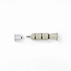
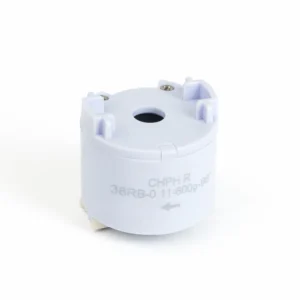
At the core of the R38L Spring Lift Mechanism is the Spring Box.
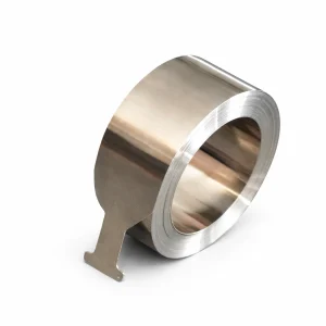
Each Spring Box contains a precision-engineered 301 stainless steel constant force spring.
The spring strip is wound in a rolled form, similar to roller shade fabric,
allowing the spring to deliver a stable lifting force throughout the entire travel range.
The Spring Box housing is manufactured from POM engineering plastic,
selected for low friction, dimensional stability, and quiet operation.
Brake Function in the Spring Lift Mechanism
The Brake plays a critical safety role in the Spring Lift Mechanism.
Its primary function is not lifting, but holding.
By preventing sudden downward movement, the Brake ensures controlled operation,
especially for large and heavy roller shades.
Spring Lift Mechanism Assembly Structure
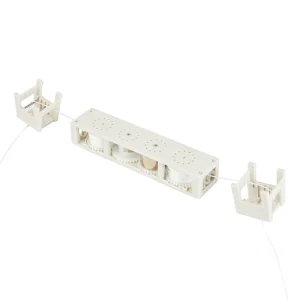
The R38L Spring Lift Mechanism is assembled linearly along the Shaft:
- The Shaft acts as the structural base
- Spring Boxes are installed sequentially
- Each Spring Box is secured using a Circlip
- The Brake is installed last to complete the system
Before insertion into the roller tube, the system must be pre-wound by three turns.
A Pin is used to lock the spring during installation.
After final installation and smoothness testing, the Pin is removed to activate the system.
Configurable Load Capacity for Heavy Roller Shades
The R38L Spring Lift Mechanism is designed for large and heavy roller shade systems.
A single Shaft can support up to five Spring Boxes.
The required spring configuration depends on:
- Total fabric weight
- Bottom rail weight
- Total shade drop
After weighing the fabric and bottom rail, the appropriate Spring Box model
and quantity are selected using the official selection chart.
Spring Lift Mechanism Selection Chart
Correct spring selection is essential for stable performance and long-term durability.
Please measure the combined weight of the fabric and bottom rail before selecting the configuration.
| Fabric/inch /cm |
36 | 48 | 54 | 60 | 64 | 72 | 84 | 86 | 96 | 102 | 112″ | Top rebound force | Unit |
| 91.44 | 121.92 | 137.16 | 152.4 | 162.56 | 182.88 | 213.36 | 218.44 | 243.84 | 259.08 | 284.48 | |||
| Spring mm | |||||||||||||
| 0.09*19*2000 | 180 | 207 | 220 | 234 | 243 | 260 | 287 | 292 | 314 | 327 | 350 | 50 | g |
| 0.10*19*2000 | 274 | 315 | 335 | 356 | 370 | 397 | 438 | 445 | 480 | 500 | 75 | g | |
| 0.11*19*2000 | 382 | 426 | 448 | 470 | 484 | 513 | 557 | 565 | 600 | 125 | g | ||
| 0.12*19*2000 | 482 | 526 | 548 | 570 | 584 | 613 | 657 | 665 | 700 | 175 | g |
Final configurations should be validated through prototype testing.
Application Scenarios for the R38L Spring Lift Mechanism
The R38L Spring Lift Mechanism is designed for roller shade systems
where standard spring solutions reach their performance limits.
It is especially suitable for the following application scenarios:
Large-Width Roller Shades

For wide roller shades, fabric weight and bottom rail leverage increase significantly.
The R38L system supports multiple Spring Boxes on a single Shaft,
allowing OEMs to distribute lifting force evenly across the width.
Heavy Fabric Roller Shades

Roller shades made with blackout fabrics, textured materials,
or laminated fabrics place higher demands on lifting and holding stability.
The R38L Spring Lift Mechanism provides controlled lift combined with reliable braking.
Commercial and Project-Based Roller Shades

In hotels, offices, and public buildings,
roller shades are often larger, heavier, and used more frequently.
The R38L system is designed to handle these higher load and durability requirements.
Premium Cordless Roller Shade Product Lines
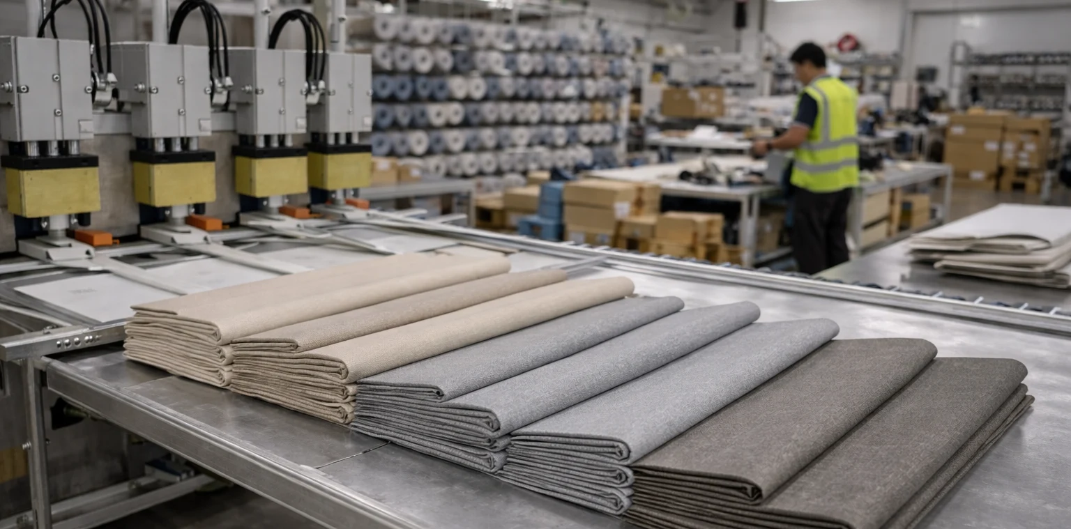
For manufacturers developing high-end cordless roller shades,
the R38L Spring Lift Mechanism offers a scalable and engineered solution
that balances smooth operation with long-term reliability.
FAQ – R38L Spring Lift Mechanism
Q1: What type of shades is the R38L Spring Lift Mechanism designed for?
The R38L Spring Lift Mechanism is designed for cordless roller shades,
particularly large and heavy fabric systems.
Q2: Why does the R38L system support multiple Spring Boxes?
Multiple Spring Boxes allow precise force matching for wide and heavy shades
instead of relying on a single oversized spring.
Q3: How do I select the correct Spring Box model?
Selection is based on fabric weight, bottom rail weight, and shade drop,
using the official selection chart.
Q4: What does the spring thickness code indicate?
Spring thickness determines lifting force.
Thicker springs provide higher force but shorter maximum travel.
Q5: Why do thinner springs support longer shade drops?
Thinner springs allow more winding turns within the same Spring Box,
resulting in longer usable travel.
Q6: What is the purpose of the Brake?
The Brake prevents sudden downward movement and provides holding stability.
Q7: Why is pre-winding required?
Pre-winding stores initial energy in the system and ensures proper operation after installation.
Q8: What happens if the spring configuration is incorrect?
Improper configuration may cause drifting, rebound, or heavy operation.
Q9: Is the R38L compatible with motorized systems?
The R38L is designed for manual cordless operation.
Hybrid systems require separate evaluation.
Q10: Who is the target customer for the R38L system?
The R38L Spring Lift Mechanism is supplied exclusively to OEM window covering manufacturers.
Field Insight
A Spring Lift Mechanism is not defined by strength alone.
Long-term reliability depends on force matching, braking authority,
and correct spring selection.
- R38L enables scalable load design using multiple Spring Boxes
- Constant force springs improve stability across full travel
- Integrated Brake prevents sudden drop in heavy shades
- Correct selection is critical for performance and durability